
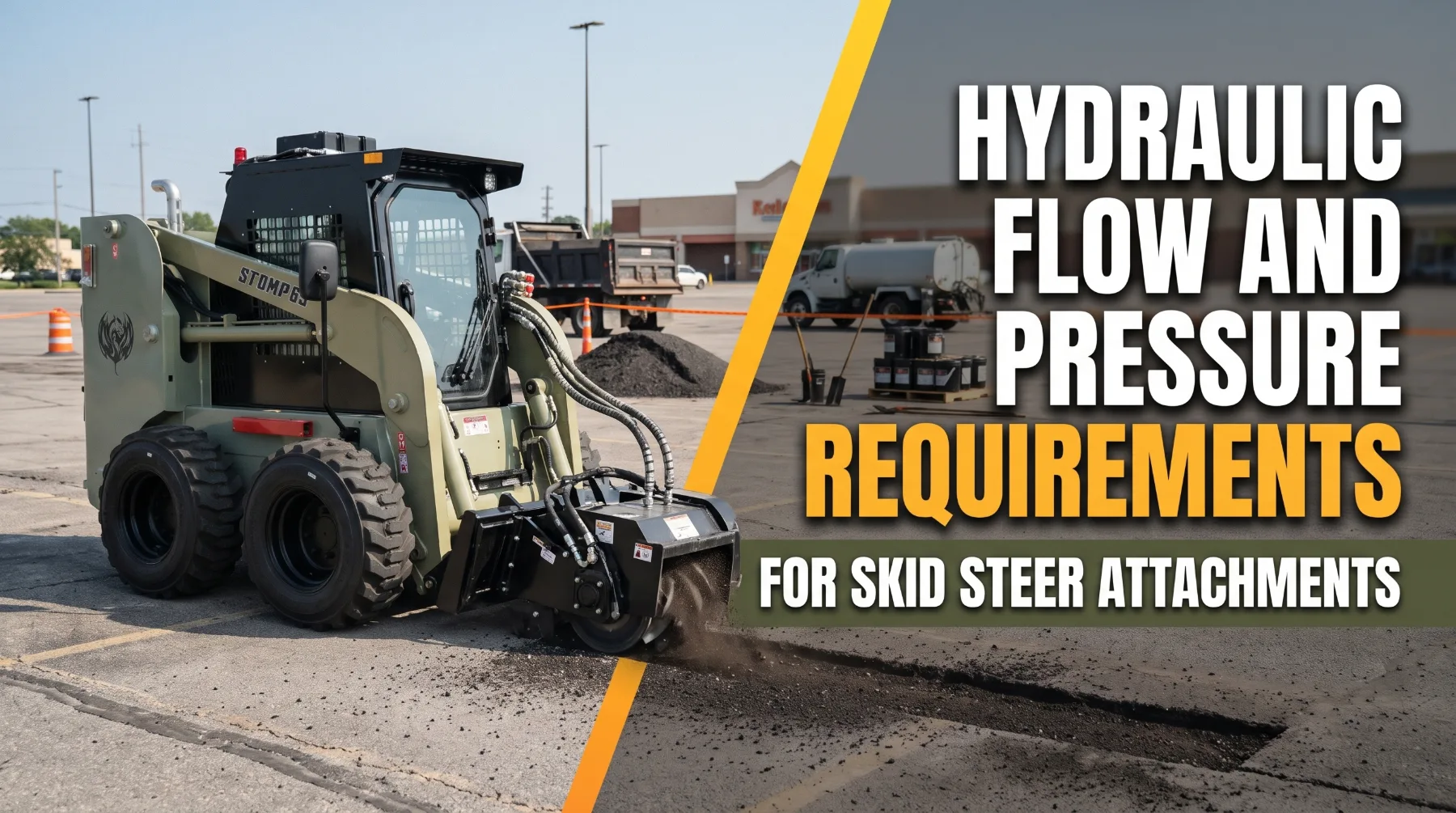
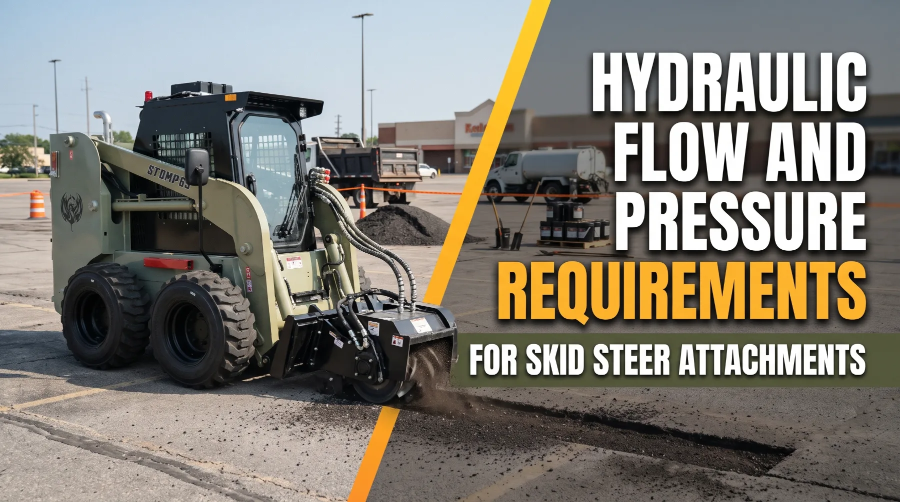
Hydraulic Flow and Pressure Requirements for Skid Steer Attachments
A property maintenance contractor rents a heavy-duty rotary brush cutter to clear overgrown drainage easements for a county contract. He connects it to his standard-flow skid steer, and the couplers snap on without trouble. The blade spins, but slowly. Within minutes it chokes on thick grass and stalls against every sapling. The cutter's decal lists a required flow well above what his machine delivers. The couplers fit and the electrical plug matched. The hydraulic requirements did not.
Skid steer attachments depend on the machine's auxiliary hydraulic system to dig, cut, drill, mulch, grind, and handle material. Physical fit doesn't guarantee hydraulic compatibility. Flow, pressure, return-line arrangement, case-drain needs, and electrical controls must all match the attachment's design. When they match, the attachment runs at its rated speed and power. When they don't, you get poor performance, overheating, and wear on both the attachment and the machine.
Understanding Standard-Flow and High-Flow Hydraulics
Auxiliary hydraulics are what turn a skid steer into a multi-purpose tool carrier. The auxiliary circuit sends oil from the machine's pump to couplers on the lift arm, where the attachment connects. Two main circuit types exist, and knowing which one your machine has is the starting point for every attachment decision.
Standard-flow circuits deliver a moderate volume of oil per minute, depending on machine size and design. That range powers many general-purpose attachments, including grapples, augers, hydraulic pallet forks, sweepers, and many trenchers and snow blowers built for standard flow. Standard-flow circuits typically use smaller flat-face couplers.
High-flow circuits deliver a significantly greater volume of oil per minute. They use a larger or additional pump, along with larger hoses, valves, and couplers. Most high-flow machines also carry upgraded oil coolers. Some manufacturers offer enhanced packages that pair high flow with higher operating pressure for the most demanding attachments, such as large cold planers and forestry mulchers.
Published auxiliary flow is usually measured at rated engine speed. At partial throttle, the pump turns slower and delivers less oil. Hoses, couplers, and valves also cause small losses before oil reaches the attachment. A qualified technician can measure actual flow and pressure at the couplers with a calibrated flow meter. That test is worth doing on older machines or before investing in an expensive high-flow attachment. Attachment size is not a reliable guide. A compact attachment may need high flow, while a large one may run well on standard flow. The attachment manufacturer's specification sheet is the only dependable reference.
Key takeaway: Standard flow and high flow describe two different output ranges, so confirm your machine's actual output at the couplers and compare it with the attachment's published requirement before buying or renting.
How Hydraulic Flow Controls Attachment Speed
Flow is the volume of oil delivered each minute, and it sets speed. In a hydraulic motor, more oil per minute means faster rotation. In a cylinder, it means faster extension and retraction. That's why the brush cutter in the opening example ran slowly. It was short on flow, not on pressure.
Motor speed follows a direct relationship between the volume of oil supplied and the motor's displacement per revolution. A motor designed to run at a certain flow rate will turn noticeably slower if starved of oil, and blade tip speed, rotor momentum, and cutting performance all fall with it. Cylinders work the same way. A grapple or clamp that receives less flow than it needs closes more slowly, which affects cycle times and productivity.
Excess flow causes its own problems. An attachment built for a certain flow range that receives far more can overspeed its motor beyond its design limit. That damages bearings and seals and sends surplus oil across the attachment's relief valve as heat. Many high-flow machines let you select standard or high flow, or set flow through the display, so one machine can run both attachment types correctly. Some attachments include their own flow control valve to protect against oversupply.
Key takeaway: Flow sets attachment speed, so supply flow within the attachment's approved range, because too little slows performance and too much can overspeed and damage the motor.
The Role of Hydraulic Pressure in Attachment Performance
Force comes from pressure, measured in pounds per square inch. Pressure produces torque in a motor and pushes or pulls in a cylinder. It builds only when the attachment meets resistance, up to the maximum set by the auxiliary relief valve. Higher pressure doesn't make an attachment run faster. It lets the attachment keep working against a heavier load.
The pressure available at the motor is the difference between inlet pressure and the pressure on the return side. If a restricted return line holds back pressure, the motor sees less effective pressure difference and produces less torque. This is one reason return-line design matters as much as the pressure rating itself.
Flow and pressure together define hydraulic power. A system delivering higher flow and higher pressure provides considerably more hydraulic horsepower than a standard-flow system, which is why high-flow machines can keep a mulcher rotor or cold planer drum at speed under load where a standard-flow machine would stall. Two machines with the same flow rating can perform very differently if their pressure ratings differ.
Relief settings must never be raised to make an unsuitable attachment work. Relief settings protect pumps, hoses, couplers, motors, and seals. Raising them can rupture components and release high-pressure oil. Some attachments are rated below the machine's relief setting, so the attachment's maximum permitted pressure must also be confirmed. Only qualified technicians should check relief settings using calibrated gauges and the manufacturer's procedure.
Key takeaway: Pressure creates torque and force while flow creates speed, and relief settings must never be raised to compensate for a mismatched attachment.
Matching Hydraulic Requirements to Attachment Types
Every attachment places its own mix of demands on the auxiliary circuit. Some need steady flow for speed. Others need high pressure for force, and some need both continuously for hours. Matching starts with the attachment manufacturer's full specification sheet, not the coupler size or the price.
General-purpose attachments such as grapples and hydraulic pallet fork positioners rely primarily on cylinder force and run well on modest flow. Augers need enough flow for useful drilling speed and enough pressure for torque in hard ground, with a planetary gearbox typically multiplying motor torque at the bit. Trenchers require a suitable balance of chain speed and torque, and high-flow versions dig faster in hard soil. Hydraulic breakers require a specific flow and pressure band and often need a free-flowing return line.

Forestry mulchers need sustained high flow and power to keep the rotor at speed as material loads vary, along with strong cooling and manufacturer-approved forestry guarding, including protective cab doors and screens. Cold planers need steady drum speed and often electrical controls for depth, tilt, and water spray. Snow blowers come in standard-flow and high-flow versions, with high-flow models handling heavier, wetter snow more effectively.
Many high-power attachments are also heavy, and rated operating capacity limits apply regardless of hydraulic compatibility. Confirm the attachment's weight against your machine's rating for the exact configuration, and never add unapproved counterweight to compensate. An undersupplied high-flow attachment often stalls under load, forces oil over the relief valve, and overheats the system rather than simply running a little slower. Use only manufacturer-approved combinations, and get compatibility confirmed in writing by your dealer before you buy or rent.
Key takeaway: Compare the attachment's flow range, pressure limit, weight, and control needs against your machine's measured output and rated operating capacity, and use only manufacturer-approved combinations.
Auxiliary Connections and Hydraulic Return Requirements
Couplers and lines carry every bit of hydraulic power to the attachment, so incorrect connections can ruin a well-matched setup within minutes. Check coupler size and type, return arrangement, case drain, and electrical controls before each installation.
Standard-flow circuits use smaller flat-face couplers, while high-flow circuits use larger couplers to carry more oil with less restriction. Forcing a high-flow attachment through undersized couplers adds back pressure and heat. Flat-face designs limit spills and keep dirt out better than older poppet styles. Wipe both halves with a lint-free cloth before every connection, inspect the seals, and fit dust caps whenever couplers are open.
Some attachments run in both directions through standard two-way couplers. Others, including many breakers and some motor-driven attachments, need a low-restriction return straight to tank. Running them through a standard return path can create back pressure that reduces torque and raises heat. Many machines also offer a continuous-flow or detent function that keeps oil moving without the operator holding a control.
Many hydraulic motors leak a small amount of oil internally to lubricate and cool their parts. That oil collects in the motor case and must return to the tank through a separate, low-pressure case-drain line. If the case drain is missing, blocked, or misconnected, pressure builds inside the case and can blow out the motor shaft seal or crack the housing. Many manufacturers recommend connecting the case drain first and disconnecting it last.
Many attachments use electrical controls for functions such as depth and tilt adjustment or chute rotation, connecting through a multi-pin connector and operating through joystick switches. Confirm that your machine's connector, wiring, and control software support the attachment. Route all hoses and harnesses so they don't pinch, stretch, or rub as the lift arms and attachment move through their full range.
Before connecting or disconnecting any auxiliary line, lower the attachment to the ground, shut down the engine, and relieve auxiliary pressure using the procedure in the operator's manual.
Key takeaway: Match coupler size, return arrangement, case-drain connection, and electrical controls to the attachment, keep couplers clean, and relieve auxiliary pressure before handling any hose.
Preventing Hydraulic Overheating and Performance Loss
Heat is the byproduct of every bit of hydraulic power that doesn't become useful work. Losses in the pump, valves, hoses, couplers, and attachment motor all end up in the oil. On continuous-duty attachments, that heat adds up fast.
Hot oil thins, which increases internal leakage in pumps and motors and slows the attachment further. Seals harden and crack. Oil oxidizes and loses its ability to lubricate. Many machines automatically reduce engine or hydraulic output at high temperature, which protects components but cuts production.

Common contributing factors include restricted or overdue hydraulic filters, cooler cores packed with dust or debris, oil of the wrong type or viscosity, excess back pressure from undersized couplers or incorrect return connections, a missing or blocked case drain, stalling the attachment against heavy resistance, and running an attachment outside its approved flow or pressure range.
Prevention follows directly from those causes. Check hydraulic oil level and filter indicators every shift. Keep cooler cores clean, and use the reversible fan where fitted. Replace filters and oil on the manufacturer's schedule, and shorten intervals in dusty or high-heat work where the manual allows. Watch the temperature gauge throughout the shift. When the attachment slows or a warning appears, reduce load and investigate the cause rather than continuing at full load. A planned stop to lock out the machine and clean the cooler takes far less time than replacing a damaged motor.
Key takeaway: Continuous attachment work generates heat that the cooling system must remove, so keep filters and coolers clean, use specified oil, avoid stalling the attachment, and investigate every temperature warning promptly.
Safe Operation, Leak Checks, and Lockout
Stored energy sits in every auxiliary circuit. Hoses and couplers hold oil under high pressure, raised lift arms hold their weight on trapped oil, and many attachments have rotors or blades that coast long after flow stops. Safe habits protect operators, technicians, and bystanders.
Set an exclusion zone sized for the attachment, since brush cutters, mulchers, and cold planers can throw debris well beyond the machine. Wear the seat belt and keep the seat bar lowered. Never bypass operator presence controls or attachment interlocks. Before leaving the seat, stop the attachment, lower it to the ground, and wait for all rotating parts to stop completely. Never clear a jammed blade, rotor, or drum while the machine is running. Only trained, authorized operators should run the machine.
Never use your hand to search for a hydraulic leak. Fluid escaping through a pinhole under pressure can penetrate skin and cause an injection injury. The wound may look like a minor puncture at first, but it's a medical emergency that requires immediate surgical treatment. Hold a piece of cardboard or wood near the suspected hose, fitting, or coupler. Wear gloves and eye protection, and keep your face and body out of line with the leak point. If anyone is struck by escaping hydraulic fluid, get emergency medical care at once and tell medical staff it's a hydraulic injection injury.
Before any inspection beyond the visual walk-around, and before every repair, follow a complete lockout sequence. Park on firm, level ground away from traffic, slopes, and edges. Stop the attachment and wait for all rotating components to stop completely. Lower the attachment fully to the ground. Apply the parking brake, shut down the engine, and remove the key. Check the auxiliary pump and verify that it is fully stopped and isolated before starting maintenance. Relieve hydraulic pressure, including auxiliary circuit pressure, as the manufacturer instructs. Apply your personal lock and tag according to your site's lockout procedure, and verify isolation before starting work.
If the lift arms must stay raised for access, engage the manufacturer's approved lift arm support device. Never work beneath raised arms or an attachment held only by hydraulics, and never rely on improvised blocking. Let hot oil, coolers, and attachment components cool before service. Leave motor, pump, valve, and relief pressure work to qualified technicians using the manufacturer's procedures.
Key takeaway: Set a wide exclusion zone, wait for rotating parts to stop, check leaks with cardboard rather than your hands, and complete a full lockout with auxiliary pressure relieved before any service.
Conclusion
Matching hydraulics to the attachment is what separates a productive skid steer from one that stalls, overheats, and wears out early. Flow sets attachment speed, pressure sets torque and force, and together they define the hydraulic power available for work. Coupler size, return arrangement, case-drain connections, and electrical controls determine whether that power reaches the attachment cleanly. Good cooling practices keep it working through long shifts.
Start with your machine's measured auxiliary output, then compare it against the attachment's full specification sheet, including weight and rated operating capacity. Have your dealer confirm compatibility in writing, and back every setup with cardboard leak checks and complete lockout before service. That approach protects your equipment investment and keeps every crew member safe.
Frequently Asked Questions
What is the difference between hydraulic flow and pressure?
Flow is the volume of oil delivered each minute and it controls how fast motors turn and cylinders move. Pressure controls the torque or force those components produce. Both are needed for performance, and together they define the hydraulic power available at the couplers.
Does every skid steer attachment require high-flow hydraulics?
No. Many general-purpose attachments, including grapples, augers, breakers, and many trenchers and snow blowers, run well on standard flow. High flow is typically required for forestry mulchers, cold planers, stump grinders, and heavy-duty brush cutters. Always check the attachment manufacturer's flow and pressure requirements.
What happens if hydraulic flow is too low?
The attachment runs slower than designed and may stall under load. An undersupplied motor turns at a fraction of its intended speed, and the attachment can also force oil over the relief valve, generating heat and shortening component life.
Why does a hydraulic attachment need a case-drain line?
Many hydraulic motors leak a small amount of oil internally for lubrication and cooling. The case-drain line returns that oil to the tank at low pressure. Without it, pressure builds inside the motor case and can blow out the shaft seal or damage the housing. Connect the case drain first and disconnect it last.